A Quest to Choose the Best Composite for a Supersonic Aircraft
By Miranda Bell, Structures Team: Materials and Manufacturing, Project Boom
You’re stuck. Hours spent researching the best material, and you’re stuck on the options that either hurt your wallet to even look at the numbers, or turn your aircraft into a flying brick with the mass of an elephant. The decision can’t be taken lightly; one wrong move and you’re the reason why 60% of the budget went into materials, or you’re the reason why the team has to make a new aircraft every year. Cheap, lightweight, or strong. You can only pick two, so make your decision wisely.
So, just how do we figure out the best material for our aircraft? As part of the Project Boom’s Structures team, specifically the Materials and Manufacturing subteam, it is our responsibility to figure out the proper criteria for a supersonic aircraft to be successful at hitting supersonic speeds, safely and non-destructively.
Materials Criteria
First things first, what do we need to look for in an aircraft? Weight. A lightweight aircraft will require less energy to get up to the required altitude. And since we’re a “simple” RC aircraft (with a complex goal), composites lead the way for the primary material of choice.
Given we’re running (well, flying) at high speeds, there are varying loading conditions acting on all regions of the aircraft; such as shear, compressive, and tensile forces. Therefore, we’re looking for composites that satisfy a base calculated tension and compressive force of 700N from previous hand calculations for a wing spanwise stress. A relatively high Young’s modulus would ensure the composite remains stiff, resisting bending and stretching. A high strength-to-weight ratio is critical to obtaining a lightweight aircraft without foregoing strength.
As the aircraft flies, due to compressibility effects (at high speeds) and skin friction, the temperature of the skin rises. Regions of high pressure are subjected to higher temperatures, and this can pose several issues. Metals lose their strength at higher temperatures as diffusion starts to occur and dislocations are able to move more freely. Composites use epoxies which have a glass transition temperature (Tg) beyond which a severe degradation in strength is observed. Hence the material choice also limits the maximum speed an aircraft can operate at. This is why the speed of the Concorde was limited to Mach 2.
A way to estimate the temperatures that can be reached is to look at the stagnation temperature of the air, which in simple terms converts the kinetic energy of the air into equivalent heat (supported by the reversibility principle of motion). The table below shows the values obtained from a simple calculator.
| Stagnation temperature calculator | |||
| Static Temp (०C) | Mach | Stagnation temp (०C) | Case |
| 15 | 0.83 | 54.839087 | < Phase 1 |
| -5 | 1.2 | 72.5152 | < Phase 2 |
| -56.5 | 2 | 117.62 | < Concorde |
Among the epoxies we are considering using, the lowest Tg is 120०C, clearly well above the temperatures expected for both phase 1 and phase 2.
Like any fledgling start-up, we must consider if the composites we’re choosing are even viable with the budget we’re working on. We can’t decide to choose the luxury options and not have a way to pay for them. Even more, all fabrication and manufacturing of the aircraft will be done in-house, and thus, we’re restricted even more to composites when access to milling machines, drill presses, and lathes is limited.
Now that we have our criteria, let’s limit the composites we need.
Composite Options
Well, there are a bunch of choices in the industry for composites: carbon fiber, kevlar, fiberglass, metallic alloys, woods, and pretty much everything that can combine to create a stable heterogeneous material that provides a significantly different end result (was Frankenstein’s monster a composite?). To shorten this list, let’s go with the aerospace industry’s choices of carbon fiber reinforced composites and fiberglass composites.
To further reduce the weight and cost of the material, a core material can be added that separates the fibers into regions of highest stress, increasing the bending stiffness of the part. In addition, a core, depending on the material and the structure type (honeycomb, foam, or wood), will provide greater resistance to compression and crush. Considerations have been made for the addition of a core, and for the next article, will be talked about in length.
Figure 2: Physical properties of various industry standard composites. N/A due to the lack of information pulled from technical sheets, and an assumption is made that the tensile strength is equivalent. 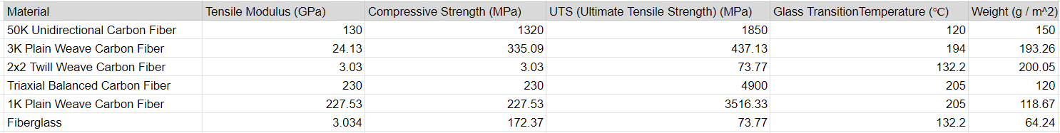
Each fiber has a tow size (the number followed by a K), which represents the number of individual carbon filaments in the tow – i.e. 12K = 12000 filaments per tow. A higher tow size would have the individual threads closer together, while a lower tow size has increased spacing. From there, each fiber has an associated weave. Unidirectional means the fibers are all woven in one direction, while plain, twill, and triaxial dictate varying angles and spacing when woven together. The direction of the weave also dictates the optimal forces each weave can take. Unidirectional weaves would be best for uniaxial forces, or forces along the same axis. Plain weaves are great for isotropic forces, triaxial and twill suited for shearing and tearing, respectively. Next, let’s move on to the costs!
Figure 3: Costs of each composite with an exception made for HDPE due to being sold in sheets.
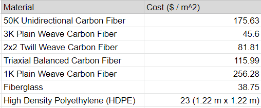
Great, we have the physical properties and costs, and now just need to rank them. However, before we do that, we need to calculate the weight each of these composites add. To not bog down the reader with multiple calculations, I included a simple calculator here! An example using 1K plain weave carbon fiber and a core of HDPE is loaded in with inputs on the left and the outputs on the right side of the calculator. We have enough information to pick our correct choice!
Composite Ranking
There’s a potential that the fiber we would like to use might be out of budget and given almost all our choices satisfy our base requirements, we just need to pick the second best option. To do this, we need to rank the fibers on a Decision, or Pugh, matrix. We take our criteria, normalize the data, add a weighting system based on importance, and rank the fibers on a scale from 1 to 5, with 5 being the best and 1 being the worst, then multiply the 1 to 5 number by the weight to create the ending values. Easy peasy… well, we hope so at least.
Figure 4: Decision matrix with non-weight and weighted choices. Note how including the weights changed our ending choice.
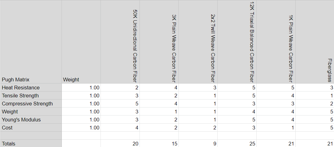
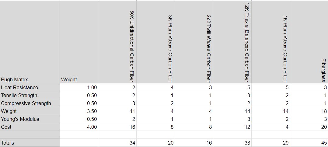
Then results are in! The data was formatted to show no decimals for readability, along with adding a weighted system to ensure we picked the right material for the job. Given our speeds, we don’t have a high enough temperature to warrant a high weight percentage, and this applies to the rest of the physical properties. In comparison, cost and weight are the most important criteria for us. Based on our chart, the fiberglass wins then is followed by the 12K triaxial carbon fiber.
Final Decisions
We have made it to the end. Our decision is no longer plagued by 20 different choices, but now we’re stuck with 2 close scores and that’s not a bad thing. Given we’re a developing team, the fiberglass option would allow us to create our prototype aircraft and test flight capabilities before moving on to the more expensive, but lightweight option of the 12K triaxial weave carbon fiber. In addition to supplementing both options with a core, we’ve officially un-stuck ourselves from our many choices. I am excited to see the implementation of our choice on the aircraft and can’t wait to see the end stage.