
Development of a Calculator for Control Surface Sizing on a Supersonic Delta Wing Aircraft
by Eber Maciel Martínez
Stabilization Control Team, Project Boom
Designing the control surfaces for a supersonic airplane is no easy task. One of the biggest challenges we face is to assure proper control at all flight regimes: from subsonic to supersonic flight. The aerodynamics of the control surfaces change considerably when going through the sound barrier. Control surface flutter, normal shocks along the wing chord and loss of control are some of the problems that may arise when going supersonic. The current design of the aircraft is constantly changing. A calculator allows us to save time and grants faster iterations while considering many design alterations. This is especially necessary because the formulas to evaluate are very lengthy. The solutions are obtained through an iterative method. We want to find the values of two independent variables that describe the size of the control surfaces when declaring the value of the dependent output of the formula. We must evaluate the formulas for small increments of each of the independent variables until we obtain the desired output. This often results in many solutions. As you may observe, it is not practical to do it manually and hence the need of a calculator.
The current design of the aircraft is constantly changing. A calculator allows us to save time and grants faster iterations while considering many design alterations.
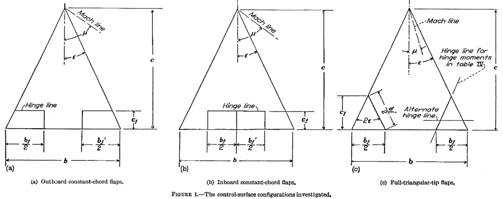
In order to achieve our goal of breaking the sound barrier, we must do our research. At the stab-con subsystem, that was the objective of the first bid. As our lead (Skyler Jacob) said, there is not a unique right answer, however there are many wrong directions. During my research, I came across a paper from the dissolved National Advisory Committee of Aeronautics (NACA) titled “Theoretical Characteristics in Supersonic Flow of Two Types of Control Surfaces on Triangular Wings” by Warren A. Tucker & Robert L. Nelson. In it, we find expressions for the lift, rolling-moment, pitching-moment and hinge-moment characteristics calculation. These coefficients are what dictate the response of the aircraft dynamics to a given input of the control surfaces. The formulas are presented for three different arrangements of control surfaces. Two of those arrangements are constant-chord flaps extending either outboard from the center of the wing or inboard from the tip of the wing, the other configuration mentioned is a triangular-tip flap. Figure 1 shows the three arrangements that I discussed, as well as defining parameters.
we find expressions for the lift, rolling-moment, pitching-moment and hinge-moment characteristics
The method of obtaining the equations is quite complex, but the general outline to follow is to first obtain the pressure distribution and then perform an integral over the proper areas and dividing by the proper dimensions to form coefficients. The author provides us with the final equations for each of the configurations above.
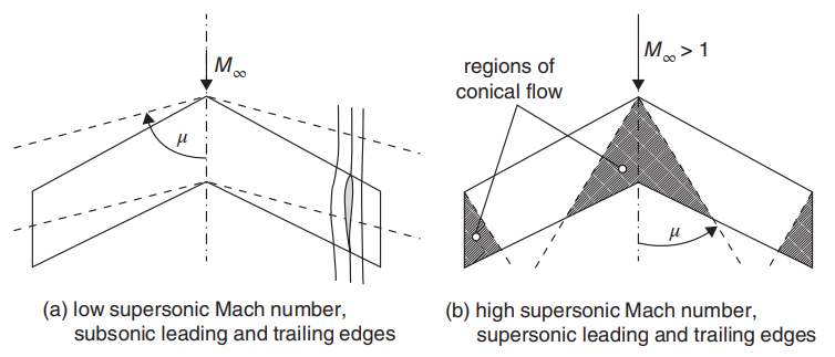
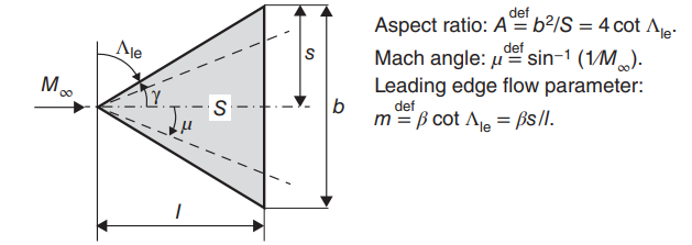
Before I dive deeper into the calculator it is worth mentioning that for each of the arrangements shown above, there are two different sets of equations: one for supersonic and one for subsonic leading edge of the wing. This can be determined through the leading-edge flow parameter, which is a function of the free-stream Mach number of the aircraft and the sweep angle of the wing. It is denoted by the letter m. If the LE flow parameter m is less than 1 then the leading edge is subsonic, if it is above 1, then it is supersonic. Once we know that, we can apply the correct formulas in order to calculate the coefficients.
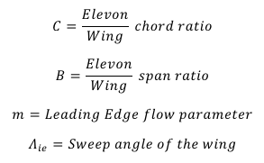
The formulas mainly consist of functions the following variables: elevon/wing chord ratio C, elevon/wing span ratio B, LE flow parameter m and the free-stream Mach number M. It is important to consider the ranges of applicability. These ranges are the maximum and minimum values of the elevon/wing ratios that will make the equation valid and are given by the author. This, in turn, creates the necessity of up to three formulas for some of the coefficients in order to satisfy various ranges of applicability. Some useful definitions are:
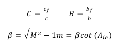
Where:
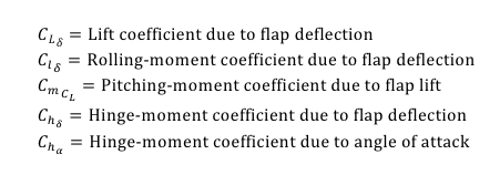
Coefficients available in the calculator

Calculator
The current design of our wing is actively changing. To accommodate these changes, Iprogrammed a calculator in MATLAB to make on the fly calculations easy. The Calculator only covers the formulas for the outboard flap arrangement since it is the one we are planning to use. The calculator works in a very simple principle:
- First, you input some constant values related to the aircraft dimensions and flight regime. Also, you can adjust the tolerance of the iterative solver.
% Control Surface Derivatives for outboard Flaps on Delta Wings
% by: Eber Maciel Martínez for Project Boom
% Formulae obtained from "Theoretical Characteristics in Supersonic Flow of
% Two Types of Control Surfaces on Triangular Wings", by Warren A. Tucker and Robert L. Nelson. NACA (1949)

clear
clc


% Constants
sweepAngle=39.48                % Sweep Angle of the wing of the aircraft
M=1.3                           % Mach number of the aircraft
beta=sqrt(M^2-1)                % Constant
m=beta*cotd(sweepAngle)         % Leading Edge flow parameter (if m<0 LE is subsonic, if m>1 LE is supersonic)
tolerance=0.001;                % Adjust this if you need a more exact iteration
E=abs(ellipticE(sqrt(1-m^2))); % Elliptic integral of the second kind for the parameter in parentheses- The next part is where we declare the values of the coefficients we want to obtain. There are two sets of coefficients, one for supersonic and the other for subsonic leading-edge.
% SUBsonic LE Desired Values
    % These are the benchmark values we want to iterate for subsonic leading edge
CL_d_sub_ref=0.5;               % Lift coefficient due to flap deflection
Cl_d_sub_ref=0.5;               % Rolling-moment coefficient due to flap deflection
Cm_CL_sub_ref=-0.5;             % Pitching-moment coefficient due to flap lift
Ch_d_sub_ref=-0.5;              % Hinge-moment coefficient due to flap deflection
Ch_a_sub_ref=-0.5;              % Hinge-moment coefficient due to angle of attack (AoA)

% SUPERsonic LE Desired Values
    % These are the benchmark values we want to iterate for supersonic leading edge
CL_d_sup_ref=0.5;               % Lift coefficient due to flap deflection
Cl_d_sup_ref=0.5;               % Rolling-moment coefficient due to flap deflection
Cm_CL_sup_ref=-0.5;             % Pitching-moment coefficient due to flap lift
Ch_d_sup_ref=-0.5;              % Hinge-moment coefficient due to flap deflection
Ch_a_sup_ref=-0.5; % Hinge-moment coefficient due to angle of attack (AoA)- The iteration section of the program is where the calculations take place and features the ranges of applicability restrictions.
%Calculations for m<1 (Subsonic Leading Edge)

%CL_d_sub
for C=0:0.01:1
    for B=0:0.01:1
        current=CL_d_sub(beta,B,C,m);
        error=CL_d_sub_ref-current;
        if abs(error) < tolerance
            if (B>((1/m)*C)) && (B<1)
                S=[C,B];
                CL_d_sub_sol=[CL_d_sub_sol;S];
            end
        end
    end
end- After running the program, a solution matrix is generated for each of the coefficients. This matrix has two columns: the left is the ratio of the elevon/wing chord “C”, and the right one is the ratio of the elevon/wing span “B”. Each pair of C and B is a solution to the formula for the coefficient given.

This calculator will save us a lot of time in the following weeks. As I stated previously, the design is actively changing and having this program ready will help us to focus on other aspects of the design. The values of the desired coefficients can be obtained from benchmarks or through an analysis of the dynamic equations. If we know how much we want the aircraft to maneuver, then we can estimate the value of the control derivative and take it as an input to the calculator.
Another thing to consider is that there exist many different pairs of solutions for B (elevon/wing span ratio) and C (elevon/wing chord ratio). It would be pretty much impossible to satisfy every formula for every coefficient with the same solution of B and C. This means that we must prioritize the results from the most critical coefficients.
All the formulas listed here are based on a supersonic flight. However, we still need to start flying from subsonic speeds and many different approaches for the sizing of control surfaces exist in that regime. We need to achieve a balance between controllability at lower speeds and higher speeds. Further investigation and testing are needed to have a complete design that satisfies the mission requirements. In the meantime, this contribution has been put to good use and allows us to be more efficient in our designs.
References
[1] Tucker, Warren A. & Nelson, Robert L. (1949). Theoretical Characteristics In Supersonic Flow Of Two Types Of Control Surfaces On Triangular Wings.
[2] Frick, Charles W. (1948). Application of the Linearized Theory of Supersonic Flow to the Estimation of Control-Surface Characteristics.